|
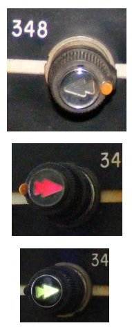
The start buttons are large and have a small arrow in the center that indicates the direction of the signal if it is valid. When the buttons are pressed the arrow in the center will turn red. When a button is pressed and a exit button is pressed and all the conditions are meet the arrow will turn green. Some buttons have a small orange or white dot on them to indicate that they can be pressed in and turned. If the button is pressed and turned to have the dot on top then it is activated for a automatic route. When it is in a automatic setting; the arrow remains red. When the button is set to automatic route it will automatically set the route the same way after a train has passed. This was for tracks that had several trains that went in the same direction and the same route. It saved the dispatcher from setting the route for every train. If the button is pressed and turned to have the dot on the bottom then it is activated for a "Restricting" aspect; the arrow remains red. The restricting signal allowed the dispatcher to put several trains on one section of track at the same time. Though the trains had to go at restricted speed which was normally 5 MPH. They were to stop short of obstruction or be prepared to stop short of train ahead. If the arrow turns green that means that a route has been aligned. If the button has been pressed and active, you can deactivate it by pulling the start button. |
|
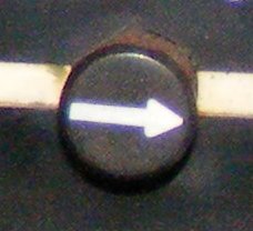
Exit buttons are the smaller buttons with a silver arrow. These were located places a train may exit. The dispatcher would push the start button then find where the train was to exit and press that exit button. |
|
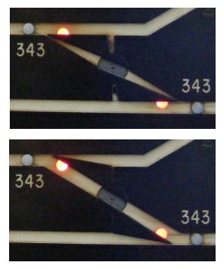
Some panels had movable switch indicators like the ones pictured to the left. They would flip from the normal position to the reverse position if the route had to go over a crossover or turnout. Sometimes these would stick and you would have to give it a touch to make them move. The top photo is of the switch indicator in the normal position; the lower photo is of the indicator in the reverse position. If a route could be set, the switches would move to the correct position and become locked. The two red lights indicate that the switch is locked and cannot be moved. |
|
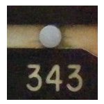
Track indicators are little white lights in the track layout that lit to indicate that a train is on that section of track. These are very important lights and they can be extremely hard to see. You can set a route while a track indicator is lit, the signal will not clear for the route until the train is off that section of track and the indicators turn off. These indicators did not tell you exactly where the train was; just that it was on that section of track. |
|
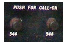
Call-On buttons are located at the lower parts of the panels. They are used when the start buttons cannot be turned to the down position. These would have a number above them to indicate what button they correspond with. They would give a "restricting" aspect just as if you had pushed the start button in and turned it down. Some panels did not have Call-On buttons; instead the start buttons would turn down. |
|
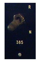
These levers were for individual switch operation and would allow the dispatcher to move the switch without setting a route. These were used to test switches, greasing switches, or to set a route and to use that switch. The N and R are for normal and reverse operations, you would pull the lever down to get the switch in the reversed position. There are little while lights under each switch lever, if you were to operate one of these the light would start to flash. This would indicate that the switch is not in the end position or is unsafe to let a train over. Once the indicator stops flashing you was to assume that the switch moved and was safe to run over. |